

Cart
0


88-108MHz DIY Kit FM Radio Transmitter and Receiver Module Frequency Modulation Stereo Receiving PCB Circuit Board
Free Standard Shipping Across USA
Vendor: Electroeshop
Type:
Sku: 14:350852#FM Transmitter Kit
Availability: In Stock
Couldn't load pickup availability
Guarantee safe checkout

Sold by Electroeshop, an authorized reseller.
Returns accepted within 30 days | support@electroeshop.com
Shipping Information
- Free Standard Shipping — United States only
- Processing Time: 3–5 business days
- Estimated Delivery: 6–10 business days after dispatch
- Double-boxed, fully insured & discreetly packaged
- Tracking number sent via email once dispatched
Returns & Refund
Returns accepted within 30 days of delivery.
Damaged or Defective Item
Free return shipping + replacement or full refund
Wrong Item Received
Free return shipping + replacement or full refund
Change of Mind
Return shipping at customer's expense · 25% restocking fee applies
All returns require a Return Authorization (RA) number before sending.
View Full Return & Refund Policy

88-108MHz DIY Kit FM Radio Transmitter and Receiver Module Frequency Modulation Stereo Receiving PCB Circuit Board - FM Transmitter Kit
$3.19

SPECIFICATIONS
Brand Name: AITEWIN ROBOT
Choice: yes
Condition: New
Dissipation Power: 1
High-concerned chemical: none
Operating Temperature: 1
Origin: Mainland China
Supply Voltage: 1
Type: Voltage Regulator
is_customized: Yes
88-108MHz DIY Kit FM Radio Transmitter and Receiver Module Frequency Modulation Stereo Receiving PCB Circuit Board
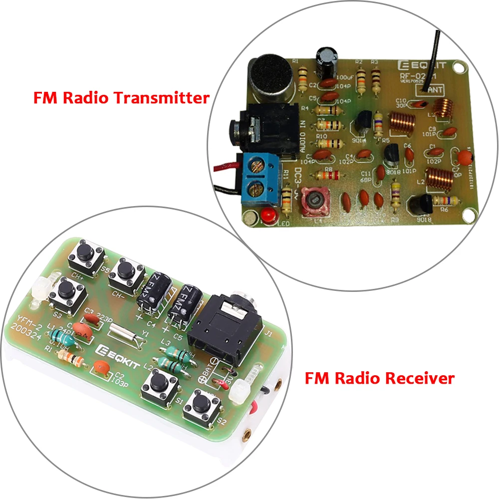
Description:
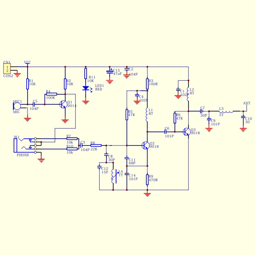
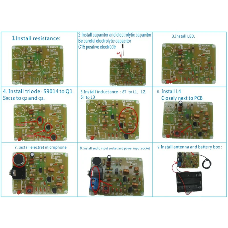
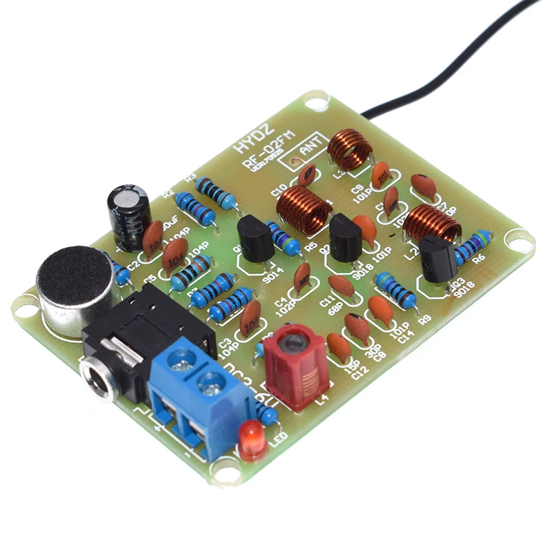
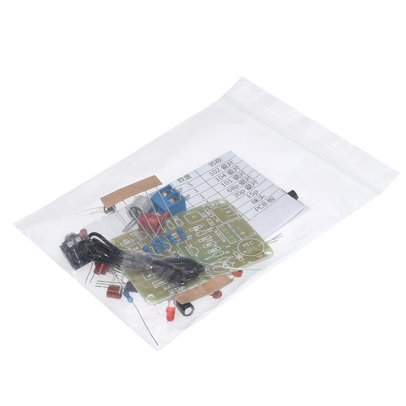
1. Model: RF-02FM
2. Operating Current: 5-15mA
3. Operating Voltage: DC 3-6V
4. Transmission Distance: 5-50m
5. Transmission Frequency: 88-108MHz
6. Audio Input: -15dB (max)
7. PCB Size: 53*40mm
76-108MHz FM Stereo Radio DIY Kit Wireless FM Receiver Module Frequency Modulation Electronics Soldering Practice Project DC 2.7V-3.3V
Note: Please don't use 18650 battery, if not it will damage the item.
Description:
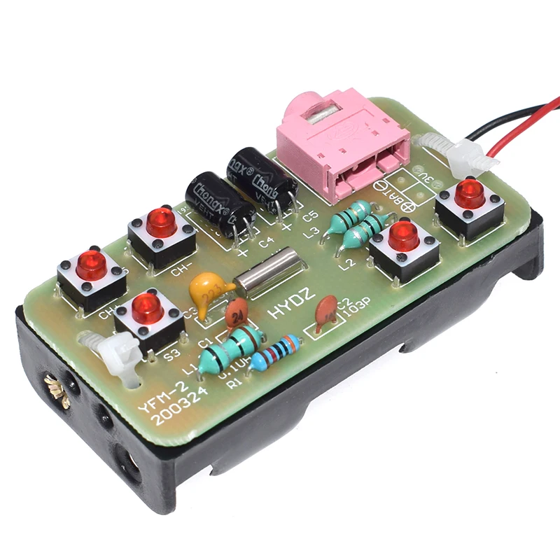
- The YFM-2 type radio circuit is very simple.
- The total number of components does not exceed 19.
- Although the number of components is not large, it includes two types of components: SMD and DIP which are suitable for novices and friends who want to practice soldering of SMD components.
Features:
1>.Built-in digital automatic gain control (AGC) circuit
2>.Support the global frequency band 76-108Mhz
3>.DIY manual welding
4>.Simple and easy to operate
5>.Support radio memory function
Parameter:
1>.Item name: FM Stereo Radio Module DIY Kit
2>.Item Mode:YFM-2
3>.Work Voltage:DC 3V
4>.Work Current:19mA
5>.Work Frequency:76-108Mhz
6>.Output impedance:32ohm
7>.Work Temperature:-40℃~85℃
8>.Work Humidity:0%~95%RH
9>.Size(Installed):57*32*20mm
Applicable:
1>.Training welding skills
2>.Student school
3>.DIY production
4>.Project Design
5>.Electronic competition
6>.Graduation design
7>.Crafts collection
8>.Home decoration
9>.Souvenir collection
Installation Tips:
1>.User needs to prepare the welding tool at first.
2>.Please be patient until the installation is complete.
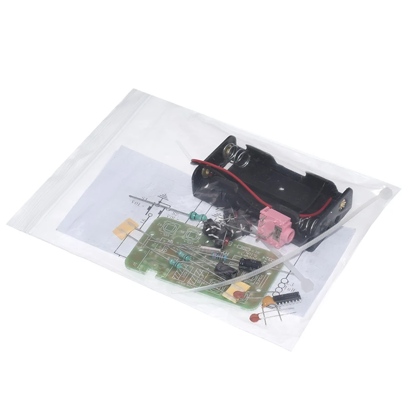
3>.The package is DIY kit.It need finish install by user.
4>.The soldering iron can't touch the components for a long time(1.0 second), otherwise it will damage the components.
5>.Pay attention to the positive and negative of the components.
6>.Strictly prohibit short circuit.
7>.Install complex components preferentially.
8>.Make sure all components are in right direction and right place.
9>.It is strongly recommended to read the installation manual before starting installation!!!
Installation Steps(Please be patient install!!!):
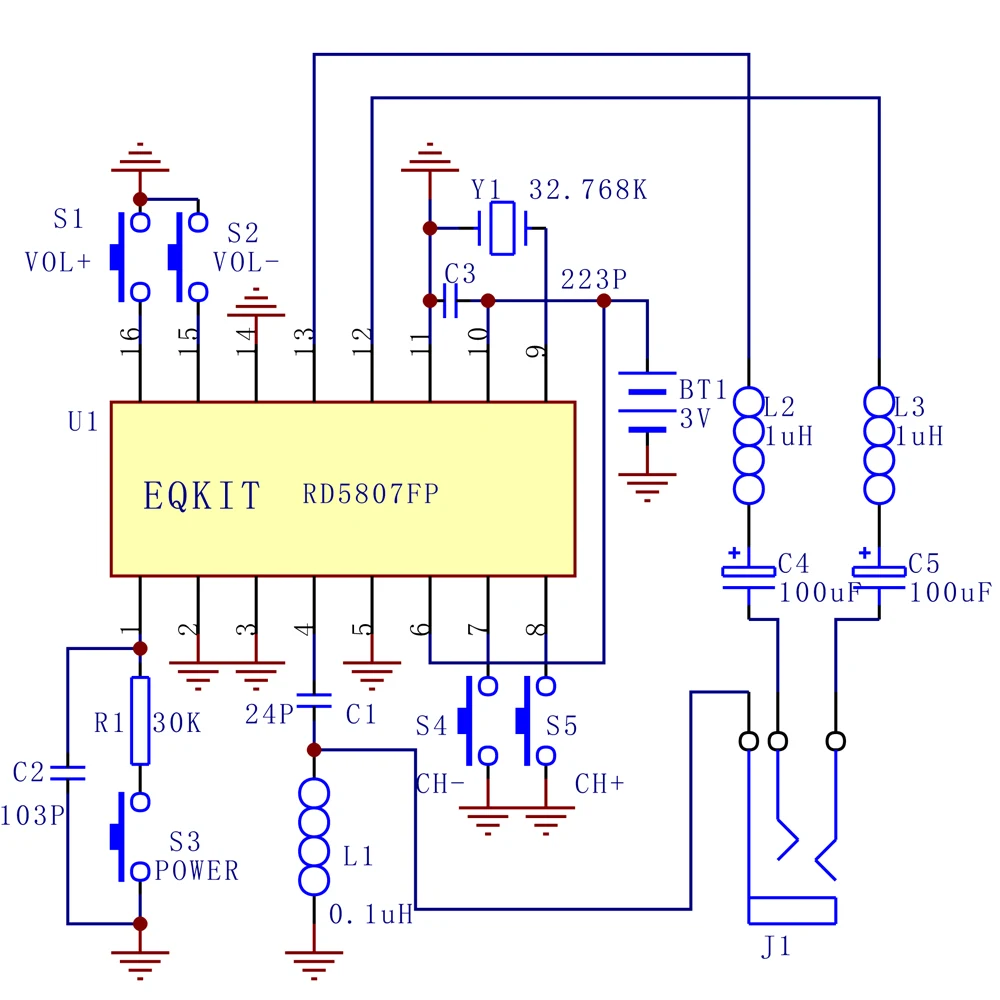
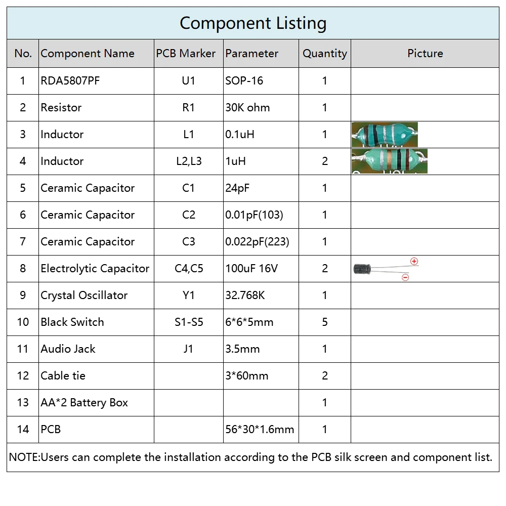
1>.Step 1: Install 1pcs SOP-16 RDA5807PF at U1.There is a dot on one corner of the IC and there is a rectangle pad on PCB where the Pin1 of IC can place on.These two marks are corresponding to each other and are used to specify the installation direction of the IC.
2>.Step 2: Install 1pcs 30K ohm Resistor at R1.
3>.Step 3: Install 1pcs 0.1uH Inductor at L1.
4>.Step 4: Install 2pcs 1uH Inductor at L2,L3.
5>.Step 5: Install 1pcs 32.768KHz Crystal Oscillator at Y1.
6>.Step 6: Install 1pcs 24pF Ceramic Capacitor at C1.
7>.Step 7: Install 1pcs 0.01pF(103) Ceramic Capacitor at C2.
8>.Step 8: Install 1pcs 0.022pF(223) Ceramic Capacitor at C3.
9>.Step 9: Install 5pcs 6*6*5mm Switch at S1-S5.
10>.Step 10: Install 1pcs 100uF 16V Electrolytic Capacitor at C4,C5. Please pay attention to the positive and negative poles. The shorter pin is the negative pole.
11>.Step 11: Install 1pcs 3.5mm Audio Jack at J1.
12>.Step 12: Connect battery box.Pay attention to positive and negative.
13>.Step 13: Use a cable tie to fasten the battery box.
14>.Step 14: Connect to power supply and enjoy the effect.
⚠️ WARNING (California Proposition 65):
This product may contain chemicals known to the State of California to cause cancer, birth defects, or other reproductive harm.
For more information, please visit www.P65Warnings.ca.gov.